
Moulded Case Circuit Breakers protect electrical systems when current rises beyond safe limits. They are widely used in commercial buildings, factories, workshops, and distribution panels. Their insulated moulded case shields internal components from dust, contact, and accidental damage. That practical enclosure matters in busy electrical rooms.
A typical breaker combines thermal and magnetic protection. The thermal element responds to prolonged overloads, such as too many machines sharing one circuit. The magnetic element reacts rapidly to short-circuit faults. This action can disconnect power before overheated conductors damage insulation or equipment. Fast isolation protects people, cables, motors, and control systems.
Size matters greatly. So does coordination.
Engineers select ratings according to load current, fault levels, cable capacity, and operating conditions. Adjustable trip settings can support better discrimination between upstream and downstream devices. For example, a branch breaker may trip while the main supply remains active. This reduces unnecessary shutdowns and helps maintenance teams locate faults faster.
In practical inspections, loose terminals, blocked ventilation, and repeated trips often reveal deeper problems. Replacing a breaker without checking the circuit can leave the real fault unresolved. That is an easy mistake. Regular testing, torque checks, and thermal scanning improve confidence in long-term performance. However, Moulded Case Circuit Breakers are not universal solutions. They still require correct installation, suitable enclosure conditions, and qualified assessment.
This article examines why these breakers remain valuable. It considers protection, reliability, maintenance, flexibility, and lifecycle cost. It also questions where their advantages may be overstated. Good protection begins with careful design.
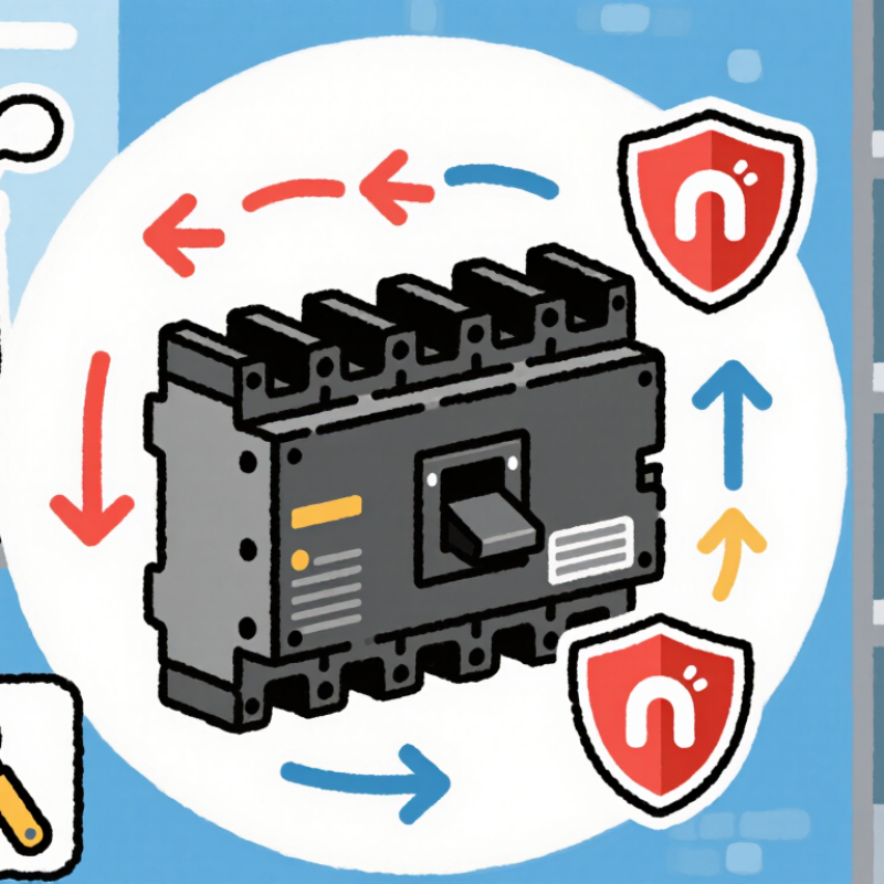
A moulded case circuit breaker carries electrical current through fixed and moving contacts. The insulated moulded case supports these parts and helps contain heat and arcing. When the handle is switched on, the contacts close firmly, allowing current to reach the connected load.
Protection begins when current becomes abnormal. A thermal trip uses a bimetal strip that bends as heat increases. This response usually handles sustained overloads, such as too many motors running together. A magnetic trip reacts much faster to a short circuit. Its electromagnetic force releases the mechanism almost instantly.
The breaker then separates its contacts. An arc appears briefly between them. Arc chutes divide, cool, and weaken this arc before it can damage nearby components. The trip mechanism locks the contacts open, even if the handle remains partly engaged. This feature prevents careless resetting.
Modern electronic trip units measure current with sensors. They can provide more precise settings for overload, short-circuit, and ground-fault protection. During site inspections, technicians usually check terminal tightness, insulation condition, and trip performance. A loose terminal may create heat without producing an immediate trip.
No breaker is perfect. Incorrect settings can reduce protection. A rushed test can also miss a developing fault. Engineers should select ratings according to conductor size, expected load, and available fault current. The breaker protects the circuit, not every possible equipment failure.
Why Use Moulded Case Circuit Breakers?
A moulded case circuit breaker combines several protective parts inside one insulated enclosure. The case resists impact, heat, and accidental contact with live conductors. Inside, fixed and moving contacts carry normal current through the circuit. An operating handle opens or closes these contacts during maintenance or daily operation.
The trip unit controls the main protective response. A thermal element reacts to sustained overloads, such as too many motors running on one feeder. It bends as heat increases and releases the mechanism. A magnetic element reacts much faster to severe short-circuit current. Its sudden force opens the contacts before conductors receive dangerous thermal stress. Some units also use electronic sensing for adjustable protection and better coordination between circuits.
The arc chute deserves attention. When contacts separate, an electrical arc can continue across the gap. Metal plates divide, cool, and weaken that arc until current stops. Terminal lugs then provide the connection between the breaker and external conductors. Small details matter here. Loose terminals can create heat, even when the breaker itself works correctly.
During panel inspections, I check connection torque, handle movement, and signs of discoloration. These checks often reveal installation problems rather than breaker failure. Protection is not magic. An incorrectly sized breaker may trip too late or interrupt normal equipment operation. I have also seen settings left unchanged after a system upgrade, which deserves careful review.
| Component or Mechanism | What It Does | Protection or Benefit | Practical Note |
|---|---|---|---|
| Moulded insulating case | Encloses and supports the breaker’s internal parts, including its contacts and trip components. | Helps provide electrical insulation and mechanical protection. | The breaker must be selected for the installation environment and used within its rated specifications. |
| Fixed and moving contacts | Make or interrupt the current path when the breaker is switched on or trips. | Disconnect the circuit when an opening operation is triggered. | Contact wear depends on operating conditions, switching frequency, and fault duty. |
| Operating mechanism and trip-free action | Opens and closes the contacts and releases them when the trip system operates. | Allows the breaker to interrupt a circuit even if the handle is held in the ON position. | A tripped breaker generally requires the prescribed reset procedure before it can be closed again. |
| Thermal overload release | In a thermal-magnetic design, a temperature-responsive element reacts to sustained overcurrent. | Trips the breaker to help protect conductors and equipment from prolonged overload heating. | Thermal response is time-dependent; the trip curve and ambient conditions affect operation. |
| Magnetic instantaneous release | In a thermal-magnetic design, a magnetic element responds rapidly to sufficiently high current. | Provides fast tripping for high-current short-circuit conditions. | Its operating threshold is determined by the breaker design and rating; it is not necessarily adjustable. |
| Electronic trip unit (where fitted) | Measures current and uses electronic circuitry to apply configured trip characteristics. | Can provide overload and short-circuit protection, with settings and features depending on the model. | Some units offer adjustable protection settings; settings must be coordinated with the system design. |
| Arc-control assembly | Guides and helps extinguish the electrical arc produced as contacts separate under load or fault conditions. | Supports reliable interruption and helps limit arc effects inside the breaker. | Breaking capacity is a specified rating and must be suitable for the prospective fault current at the installation point. |
| Terminals and conductor connections | Connect the breaker to the supply and load conductors or busbars. | Provide the electrical interface for circuit protection and isolation. | Conductor size, terminal compatibility, and tightening requirements should follow the breaker’s instructions. |
| Manual switching and isolation | Allows an operator to open or close the circuit using the breaker’s operating handle. | Provides a means of switching the circuit and, when open, separating the circuit contacts. | A breaker should not be treated as a substitute for safe isolation and verification procedures. |
Moulded case circuit breakers protect feeders, motors, and distribution panels from overloads and short circuits. Their compact insulated housings also reduce exposure to live internal parts. In practical installations, correct ratings matter more than physical size.
Rated current, or In, defines the continuous current the breaker can carry. Engineers should compare it with cable capacity, ambient temperature, and expected load cycles. A breaker that looks suitable may still require derating inside a hot enclosure. Small details matter.
Rated operational voltage must match the system voltage. Breaking capacity is equally important. Icu shows the maximum fault current the breaker can interrupt under specified conditions. Ics indicates a service-level breaking capacity and often supports continued operation after a fault. These values should exceed the prospective short-circuit current at the installation point.
Trip characteristics influence real performance. Thermal protection responds to sustained overloads, while magnetic protection reacts quickly to severe faults. Electronic trip units can provide adjustable long-time, short-time, and instantaneous settings. Poor adjustment can cause nuisance trips or delayed protection. That is not a minor inconvenience.
Pole configuration, insulation voltage, impulse withstand, and mechanical endurance also deserve review. Selectivity between upstream and downstream devices can keep one fault from shutting down an entire panel.
IEC 60947-2 provides a useful technical reference, but field conditions still require verification. Specifications are helpful. Measurements are better. A final check should include conductor size, connection torque, enclosure temperature, and available fault current.
Why Use Moulded Case Circuit Breakers?
Advantages Over Other Circuit Breaker Types
Moulded case circuit breakers offer stronger protection for commercial buildings, workshops, and industrial distribution panels. Their insulated cases protect internal parts from dust, impact, and accidental contact. Compared with miniature circuit breakers, MCCBs usually handle higher currents and greater fault levels. That extra capacity matters when large motors, heaters, or multiple machines share one feeder.
Many MCCBs combine thermal and magnetic protection. Thermal protection responds to sustained overloads, while magnetic protection reacts quickly to short circuits. Some models also provide adjustable trip settings, allowing engineers to coordinate upstream and downstream devices. This selectivity can keep one faulty branch offline while essential equipment continues operating. Unlike fuses, MCCBs can be reset after a trip, reducing replacement work and improving maintenance efficiency. The result is easier fault investigation.
Practical installation still requires care. I have seen protection settings left at factory values, even after equipment loads changed. That weakens the benefit of adjustability. Engineers should verify cable ratings, prospective fault current, enclosure conditions, and local electrical requirements. Regular testing helps confirm that the mechanism trips reliably. MCCBs are not automatically the best choice; smaller circuits may need simpler protection, while sensitive personnel protection may require separate residual-current devices. Their real advantage appears when higher capacity, adjustable protection, and maintainable operation must work together.
MCCBs can serve circuits with higher current requirements than typical MCBs, while offering a more compact alternative to many air circuit breakers.
Typical illustrative ranges in amperes; actual ratings vary by device and manufacturer, and ranges can overlap. Select a breaker based on the installation and applicable standards.
Why Use Moulded Case Circuit Breakers?
Typical Applications and Selection Considerations
Moulded case circuit breakers are commonly used in commercial buildings, factories, and service panels. They protect circuits feeding pumps, compressors, lighting systems, and distribution boards. A pump room, for example, may need a breaker that handles motor-starting current without nuisance trips. Yet it must still disconnect safely during a fault.
Selection starts with the system voltage and the expected continuous load. Check the breaker’s rated current and interrupting capacity against the available fault current. Trip characteristics matter too: a motor circuit may need different protection from a lighting feeder. A breaker that fits physically may still be a poor choice electrically. That is an easy detail to miss.
Also consider ambient temperature, enclosure conditions, cable size, and coordination with upstream and downstream devices. In a warm panel, heat from neighboring equipment can affect performance. Leave room for inspection and planned maintenance; cramped installations make simple checks harder. Consult the equipment documentation and have a qualified electrical professional verify the design. Ratings alone do not tell the whole story, and site conditions can complicate an otherwise tidy selection.
1901 West Main Street
Washington, MO 63090
Main Directory: 1-800-227-4873
Email: sale@pangcofurniture.com

We’re always looking for talented individuals to join our team. Send us your resume using the form below. When a position comes available that matches your skillset, one of our team members will reach out to you.
"*" indicates required fields